Starter 5 Running LED With Arduino
Arduino Turn LED ON and OFF With Button The Robotics BackEnd
How to Make an Arduino Running LED - LED is a basic component in Arduino learning. Almost all electronic equipment uses LEDs. Such as TV, Radio, SmartPone, Hard Disk, Mouse, Keyboard, Router, washing machine, and many more. Not only on electronic devices, the use of LEDs is also in automotive such as spotlights on cars.

Tutorial Arduino Simulasi Running LED Proteus 8
Control of the LED screen. Control of the LED screen. Skip to main content. Command Line Interface Visual Studio Code support Coding on Raspberry Pi Blocks Embed. Docs Reference Led. on pin pressed button is pressed compass heading pin is pressed temperature acceleration light level rotation magnetic force running time set accelerometer.
Starter 5 Running LED With Arduino
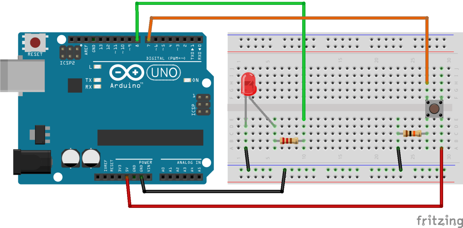
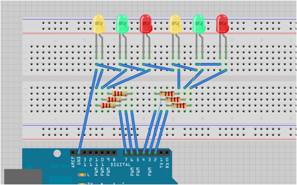
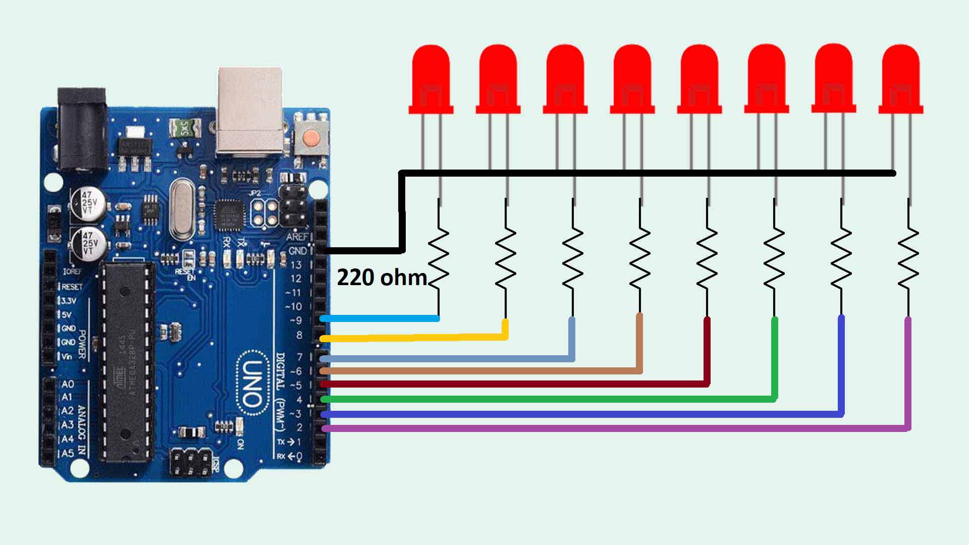
Connect the Circuit as shown in the diagram above or as shown in the schematic below; Connect the anodes of the LEDs to pins 7,8,9,10 of Arduino respectively. Connect a 1k resistor from the cathode of LED to the ground (-) rail on the breadboard
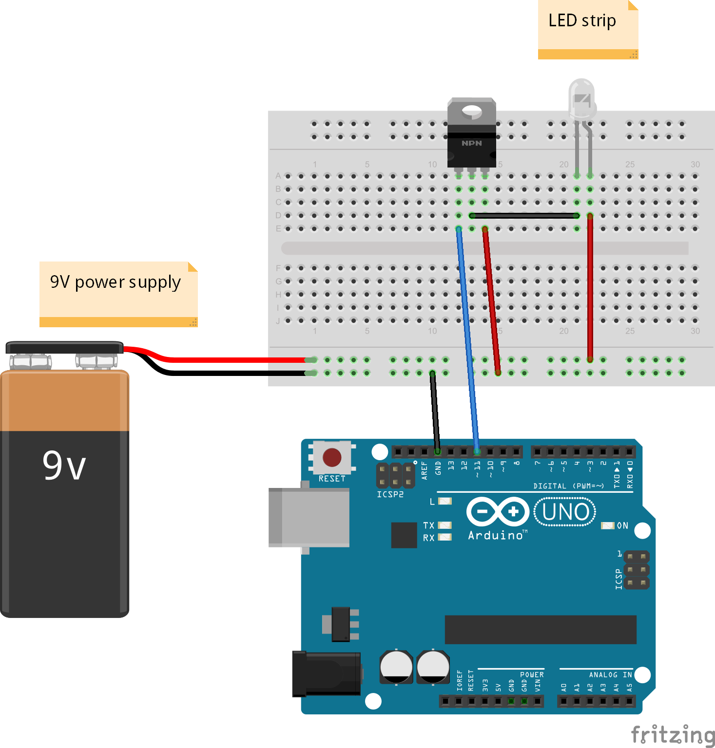
Driving a LED strip with Arduino Yet Another Arduino Blog
Generally, daytime running lights must be approved for road traffic. To obtain this, they must therefore fulfil the specifications according to ECE-R87. Once the light passes the so-called type approval, the approval is granted. Generally, the approval mark can be found on the lens or the housing. 2578 Approval number.
Getting Started with the Arduino Controlling the LED (Part 1)
On the computer, add the downloaded library to the Arduino library folder. Open the library and use the steps below to navigate the initial set up. On the second line of code, put in how many LEDs you are running. Specify the type of LED strip you are running based on the integrated circuit chip of your addressable LED strip.

Led Running Light Circuit Diagram
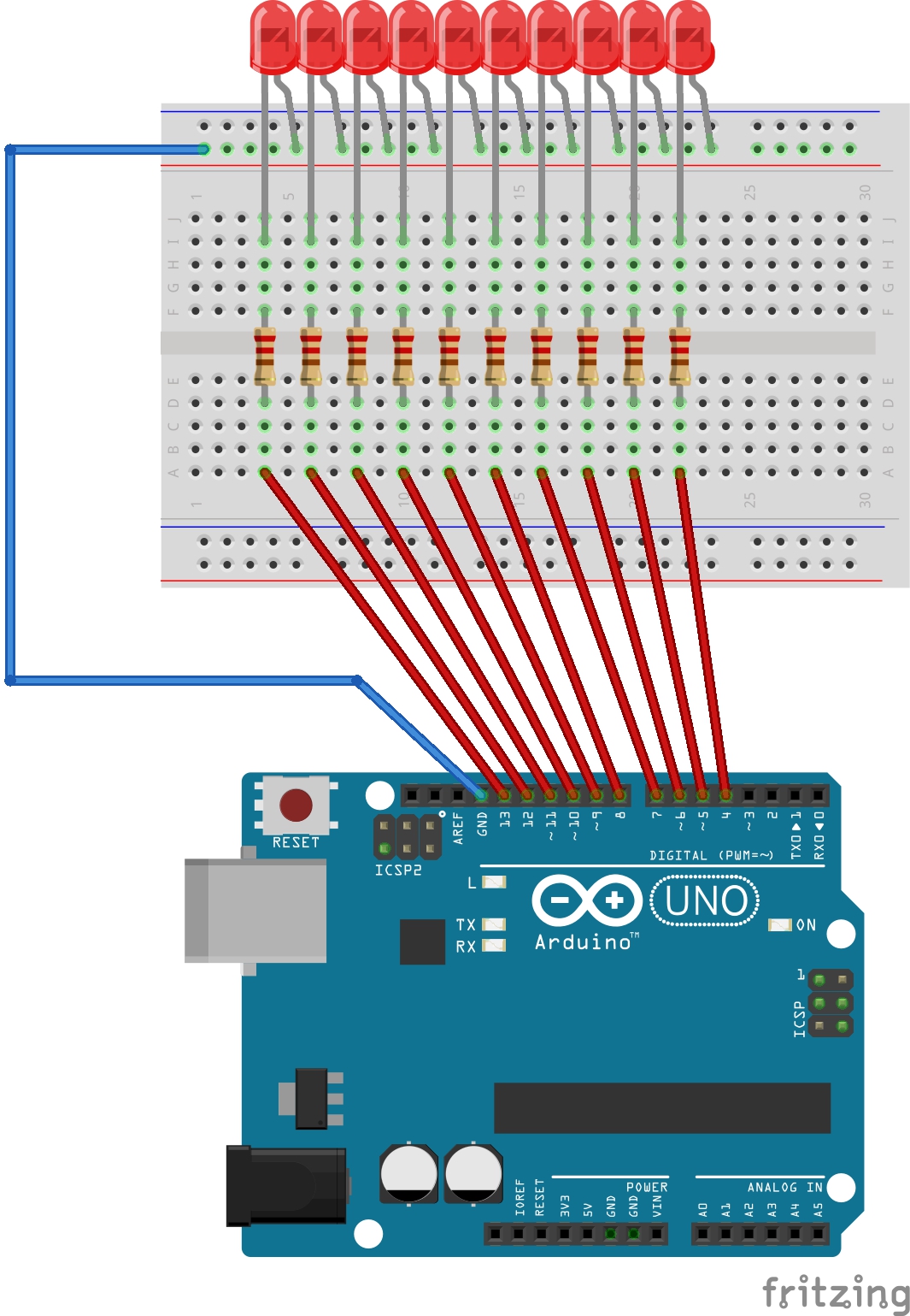
Connect all the LEDs and resistors to the breadboard. connect the arduino uno to your PC. Read the code, understand it (you can change the delay time and the order of the scrolling) and upload it to your board.

How To Run Led Matrix Studio Designs On Arduino ledmatrixstudio
About LED Pinout LED includes two pins: Cathode (-) pin: needs to be connected to GND (0V) Anode (+) pin: is used to control LED's state How It Works After connecting the cathode (-) to GND: If connecting GND to the anode (+), LED is OFF. If connecting VCC to the anode (+), LED is ON.

Running Led Lights Circuit Diagram Wiring Diagram
Usually, the LED's shortest lead connects to the ground side. If you connect the LED to pin 13 as shown in the image below, you can use the same code we used above to make the LED flash on and off. Changing the Pin. If you want to use a different pin to power the LED, it's easy to change it. For example, say you want to use pin 8 instead of.
Arduino LED Blinking Tutorial 2 MakerStream
What are the easiest steps to make a small circuit with an LED flash from a C/C++ program? I would prefer the least number of dependencies and packages needed. What port would I connect something into? Which compiler would I use? How do I send data to that port? Do I need to have a micro-processor?
led circuit diagram arduino Wiring Diagram and Schematics
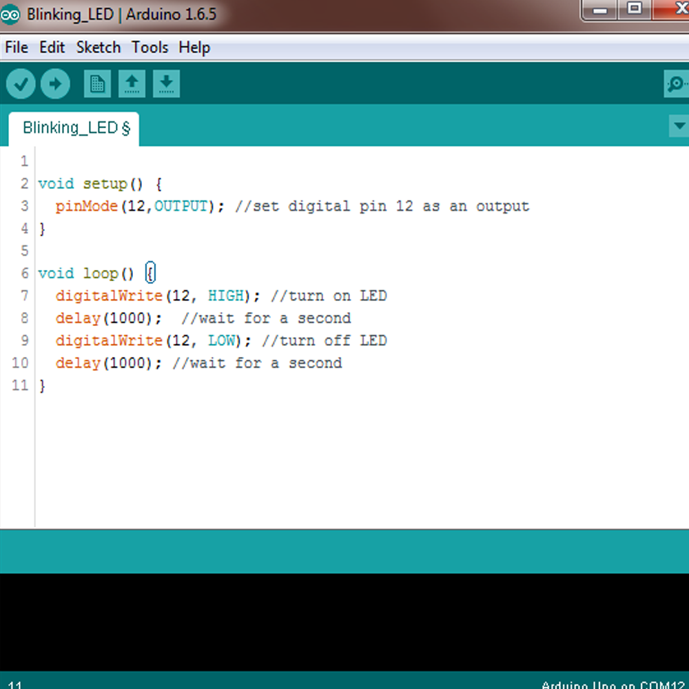
In the main loop, you turn the LED on with the line: digitalWrite (LED_BUILTIN, HIGH); This supplies 5 volts to the LED anode. That creates a voltage difference across the pins of the LED, and lights it up. Then you turn it off with the line: digitalWrite (LED_BUILTIN, LOW); That takes the LED_BUILTIN pin back to 0 volts, and turns the LED off.

HOW TO MAKE ARDUINO runing LEDs YouTube
Over 90% Of All Products On eBay Are Brand New. Big Brands, Top Retailers. Great Prices On Millions Of Items. Get It On eBay.

Chasing LED Lights With Arduino Code YouTube
MAX 7219 is a common cathode display driver with serial input and parallel output. It is used to interface microprocessors and microcontrollers with 64 individual LEDs. The 8 x 8 LED matrix is connected to the MAX 7219. The data input is received from the Arduino board to the MAX7219.

BELAJAR ARDUINO Running LED Ahmad Zipur
Quick Steps. Connect Arduino to PC via USB cable. Open Arduino IDE, select the right board and port. Copy the above code and open with Arduino IDE. Click Upload button on Arduino IDE to upload code to Arduino. Press and keep pressing the button several seconds. See the change of LED's state.

Running LEDs Arduino Uno 4 Steps Instructables
LEDs LED Light LED stands for light emitting diode. It has a positive and negative lead. The longer side is the positive lead. How to assemble the components In this project, we are only going to make the LED blink. First, we need to plug in the USB Cable to the board and then the computer.

Running Led Circuit Diagram Pdf
Running LED Basic Arduino TutorialThis is a simple tutorial about how to connect and to program 12 LEDs with Arduino UNO to create a nice light effect.Vrlo.
Load Wiring Ditrio Led Wiring Diagram
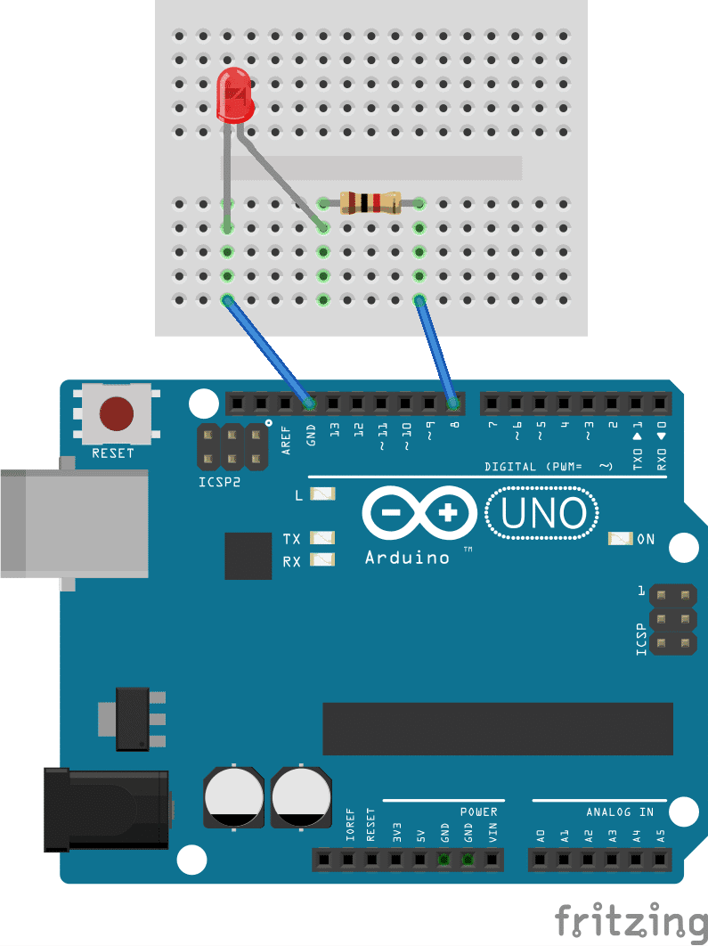
Build the circuit. Here is the circuit. How to build the circuit: First make sure that the Arduino is powered off (no USB cable plugged to anything). Check the LED, you will see that one of the leg is shorter than the other one. Plug the shorter leg of the LED to a hole on the breadboard.
